- OTDRs
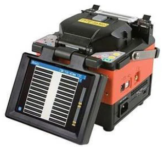
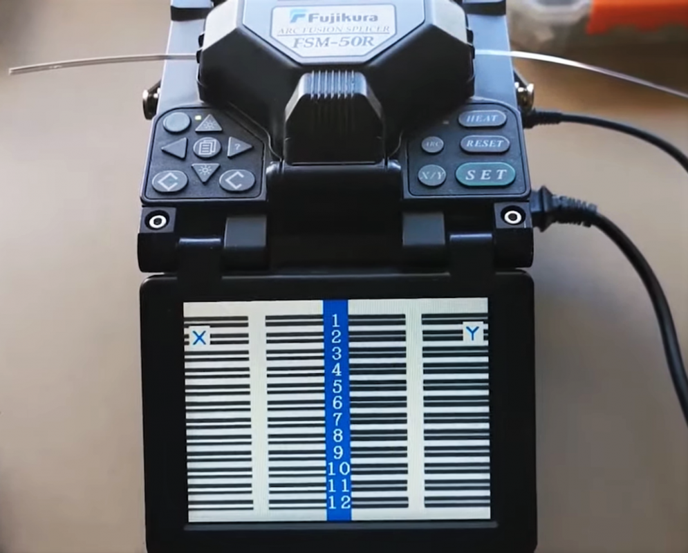
- Fusion Splicers
- Network & Ethernet Testers
- Cable Certifiers
- Wireless, Antenna & 5G Testers
- Fibre Optic Inspection Scopes
- Power Meter, Light Source, OLTS
- NBN Compliant Equipment
- DSL, ISDN, Copper, HFC, CATV Testers
- Fibre Optic Accessories
- Fibre Traffic Identifiers
- Cleavers
- OTDR Launch Cables
- Optical Fibre Adapters and Test Leads
- Spectrum Analysers
- Fiber Characterisation Test Equipment
- Electrical Test Equipment


OTDR Testing criteria and standards for NBN Australia National Broadband Network, Telstra, Optus and TPG

What are OTDRs?
It is Fibre optic equipment used to characterize, troubleshoot, and maintain optical communication networks. OTDR testing criteria are based on transmitting and analyzing pulsed laser light propagating through an optical Fibre. This testing is unidirectional, meaning the light is inserted at the end of the Fibre optic cable link.
Using information gleaned from the resulting optical signature reflected or backscattered to the origin, an OTDR acts as an optical radar system to determine the location of splices, connections, defects, and other features of interest and overall Provides detailed information about the state of the user.
Understanding the Components and Operation of an OTDR
OTDRs consist of :
- Laser light sources and laser diodes emit light pulses on command from the controller.
- The coupler/splitter has three ports. 1/ for the light source, 2/ for Fibre under test, and 3/ for the sensor. This device allows light to travel only in specific directions from the laser source to the Fibre under test, from the Fibre under test to the sensor.
- An optical sensor is a photodetector that measures light’s power level from the Fibre under test and converts light’s optical power into the corresponding electrical level. Controller section, the controller is the “brain” of the OTDR.
- Tell the laser when to pulse.
- Receives power level from the sensor
- Calculate the distance to the scattered and reflected points in the Fibre
- Save individual data points.
- Send information to the display section.
- Display Section The display section is a CRT or LCD screen that displays the data points that make up the Fibre trace.
- User controlled. The OTDR’s keypad and touchscreen controls allow operators to change settings to best suit their work environment. The operator can ultimately maintain the OTDR or “auto” control.
Key Components and Functions of an OTDR Explained
An OTDR contains:
- A laser diode light source.
- A photodiode detector.
- A precision timing circuit
Lasers emit pulses of light at specific wavelengths. This pulse of light travels down the Fibre under test. As the pulse travels down the Fibre, some transmitted light is reflected/refracted or scattered back down to the photodetector. OTDRs. The intensity of this return light and the time it takes to return to the detector give the value of loss (insertion and reflection), the nature and location of the event within the Fibre link.

OTDR Working Principle
The accuracy and usefulness of OTDR testing would not be possible without prior science. Understanding the physics behind the equipment provides valuable insight into how an OTDR works. When Albert Einstein theorized that electrons could be excited to emit specific waveforms, the seeds of what would eventually lead to the first practical lasers were born in 1960.
The applications envisioned at the time probably did not include global telecommunications over Fibre, but today the technology is synonymous with 21st-century connectivity. Over the years, many groundbreaking discoveries have been incorporated into the development of OTDR testers.
OTDR Basics and Functions
The inherent cost of OTDR trying outcomes from diagnosing the situation of a Fibre optic cable could be impossible to see in any other cases. The hyperlink must consist of more than one splice and connections that may be difficult to fail.
The optical go-back loss (ORL) and reflectance may be used to diagnose situations in which extra loss than predicted is going on at a selected place withinside the Fibre run. The general Fibre attenuation can also be assessed when considering that the quantity of backscatter affords a demonstration of this cost.
These similar concepts are used to calculate distance measurements which can be worthwhile while repair, troubleshooting, or upkeep wishes arise. The give-up of the Fibre hyperlink or a Fibre smash could be detectable thru Fresnel mirrored image when you consider that a success or unterminated Fibre give-up is likewise an extra in fabric media (glass to air).
In addition to the general time duration, the Fibre may decide the gap between faults, splices, and connections with a graphical presentation of the analysis’s findings.
Where to Use an OTDR?
There is a good deal of confusion about how and in which to apply an OTDR efficiently. With specific packages of Fibre optic cables in Premises cabling and Outside Plant (OSP) cabling, the capability of the OTDR additionally varies.
In Outside Plant cabling with more than one splice, the trying out tool is vital and regularly used to ensure that the cable isn’t broken and that every splice is assembled correctly. It additionally facilitates troubleshooting issues like finding the breaks withinside the line.
On the opposite hand, premises cabling consists of brief cable runs. It seldom includes splices, so that the Optical Time Domain Reflectometer may have appeared as an alternative for insertion loss trying out with an energy meter and mild source. However, the rate of OTDR is ten instances of insertion loss trying out equipment.
How to Use an OTDR to Check Fibre Cables?
Trying out the tool can use a release cable alongside a get hold of line or best the release cable. However, the trying-out consequences in each eventuality could be specific.
Testing with Launch Cable
The high-energy look at the pulse used within the trying out overloads the instrument’s receiver so that no measurements may be made. It will make the tool blind for that period. The tool will try to get over this, inflicting a useless area.
A useless area is an essential parameter in OTDR. It is the gap within the cable where the fault or defects can’t be measured efficiently.
Why do Dead Zones Occur?
If a top part of the sign is reflected, the obtained energy is more than the backscattered energy level. It floods the OTDR with mild, making it blind. The Optical Time Domain Reflectometer calls for a while to get over this blind section or saturation. During the restoration section, the reflectometer cannot come across the backscattered mild, ensuing in a useless area within the hint or signature.
Generally, dead zones are of types:
- Event Dead Zone or EDZ
- Attenuation Dead Zone or ADZ
One can triumph over the useless area via means of the use of a release cable with OTDR. A release cable will region the desired duration of Fibre among the take a look at cable and OTDR, supplying the gap and time required via the means of the tool to efficiently degree the Fibre cable characteristics.
Launch cables no longer intrude with the line beneath neath check, making it a stable manner to become aware of faults within the entire duration of the optical Fibre.
Testing with Receive and Launch Cable
The obtain and release cables incorporate spools of Fibre with unique distances. The wires are generally related to the ends of the check Fibre cable to qualify the front-cease and far-cease connectors. Each of those cables relies upon the duration of the cable being tested. For multimode testing, the time is typically between 300-500 m and 1000-2000 m for single-mode testing.
For the very lengthy haul, you may use cables of 4000 m. The duration of the cables additionally relies upon the pulse width. The larger the pulse width, the longer the release time and obtain cables. It is crucial to notice that each cable must be similar because the cable beneath neath checks.
OTDR Types
As the practical application of OTDR trying out will increase alongside the call for more incredible trying out speed, accuracy, record technology, and garage competencies, the variant in product services keeps diversifying.
- The elementary classes are bench-pinnacle and handheld. A bench-pinnacle OTDR is a feature-wealthy device with a right-away AC strength source.
- At the same time, a handheld or compact OTDR is generally a lightweight, battery-powered tool supposed to be used inside the field.
Beyond this simple division, the functions and alternatives for an OTDR have to be cautiously taken into consideration, primarily based totally on the supposed use.
- One vital attention is the kind of Fibre you may be trying out multimode, single-mode, or both.
- Another variable is the duration of Fibre you may be trying out.
Products designed for long-haul programs generally have better dynamic variety competencies that could now no longer be required for trying out shorter Fibre optic links, which includes FTTA.
Usability functions additionally range with the aid of using the product. Still, for any other purpose, the supposed utility for the OTDR has to be the top vital thing in product selection (Import elements for selecting an OTDR).
- For example, a lightweight product may not be vital for a desk-bound test. However, if the trying out goes to be carried out with the aid of technicians hiking molecular towers or operating in any other case, energetic setting, weight, and functions like battery existence and ruggedization of the product enclosure, emerge as extra vital.
OTDR Testing Parameters
OTDR testing has various applications, and setting parameters to the task ensures accurate measurements. For some tests, it may be sufficient to use the autotest feature. Still, given the differences in Fibre link length, type and complexity, it is recommended to set the parameters manually.
Once the correct parameters for testing a particular Fibre run are established, the industry engineers can recall OTDR test configurations from the instrument’s memory the next time the same or similar run is evaluated.
National Broadband Network (NBN) Australia
According to the latest report about the NBN Australia that: Remote monitoring technology means NBN should no longer need to send out its technicians to verify reported Fibre faults on the Transit Network: the backbone of the NBN broadband access network.
Instead of expecting to be able to remotely identify the location and nature of a given problem, anywhere from Bermagui to Broome through the Network Operations Center (NOC) in Melbourne.
NBN Co’s Dense Wavelength Division Multiplexing (DWDM) Fibre-optic transit network comprises DWDM nodes situated at Points of Interconnect (POIs), Fibre Access Nodes, and Intermediate Access Point sites, physically connected by more than 70,000 kilometers of Fibre across the nation.
The Old/ Traditional Approach
When there’s a Fibre fault, NBN Co must provide Optical Time Domain Reflectometer (OTDR) measurements to third-party Fibre providers, like Telstra, Optus, and TPG to rectify the fault.
Until now, they needed to send a field engineer to the site, armed with a handheld OTDR, to perform measurements and provide the required OTDR trace to our third-party Fibre providers. This process takes one day in metropolitan areas and four days in remote areas.
In NBN Co Australia, A third-party Fibre optic provider such as Telstra, Optus and TPG organized its field service to fix the fault.
New Approach
In the new system, physical devices will be installed at various locations in Australia, controlled remotely via a web-based user interface, and managed by an element management system.
OTDR remote test units will eventually be installed at his 300+ sites in existing DWDM racks, and NBN Co, through his NOC, will be able to monitor over 90% of his DWDM transit networks
According to the Transit Network team, this new approach not only improves network availability by identifying faults more quickly but also reduces costly “truck rolls” (e.g., It is also helpful in avoiding ground). Improved network availability also reduces downtime and increases end-user customer satisfaction.
According to Senthil Manikandan, In 2017, the NBN access network integrated Tier 3 DWDM Transmission Technology Manager at NBN Australia as their first Fibre remote monitoring system.
“The challenging deployment schedule, which included highly remote locations, was enthusiastically received by field engineers and other integration resources statewide, resulting in a very positive and budget-friendly outcome for NBN Co Australia.”
The system is already operational and, to date, has been deployed by the NOC with 148 remote OTDR test units in a transit network covering 565 Fibre links. Six ‘Fibre incidents’ have already been confirmed, including one near Broome in northern Western Australia.